Single-Hand Container Opener
A user-centered engineering design project rethinking how people with limited hand mobility open everyday containers — independently, comfortably, and with one hand.
Introduction & Problem Statement
The Problem Space
People who have had an amputation in their upper limbs and those with conditions that affect their ability to grip (including arthritis, stroke recovery and repetitive strain injuries) struggle to open everyday containers without assistance. Standard containers are designed to be used by two hands, one to hold the container and the other to twist, pull, or pry open the lid.
Existing assistive tools each solve a portion of the problem but are lacking. Electric openers are costly, need tabletop space and are not compatible with all lids. Under-cabinet openers are permanently installed and are designed to work with jars. Rubber grip pads still need an extra hand to hold on.
Who Is Affected
Our primary users are people with one arm or hand (congenital or acquired), people recovering from upper-limb injuries, and older adults experiencing age-related grip decline.
Stakeholder Research
Research Methods
Our team conducted stakeholder research through direct observation of the target use case, review of existing assistive-technology literature, and structured analysis of user needs.
Key Findings
- Containers slide: without a second hand to anchor the container, it moves across the countertop when force is applied to the lid, making it impossible to generate sufficient torque.
- Two actions required simultaneously: almost every lid type requires holding + twisting at the same moment.
- Existing solutions are too specialized: most products target a single container type and do not generalize.
- Users prioritize independence and dignity: needing to ask for help with a basic kitchen task is demoralizing.
Stakeholder Priorities
Ethical Considerations
We decided not to create a "powered device" solution. The design is intended to be unobtrusive and not stand out as a sign of the user's handicap. We focused on materials and manufacturing processes that would ensure the finished product would be cost effective.
We recognize that our team does not consist of those who have lived experience with a ULD. Future research will need to be done in collaboration with the user community.
Ideation & Concept Development
Brainstorming Process
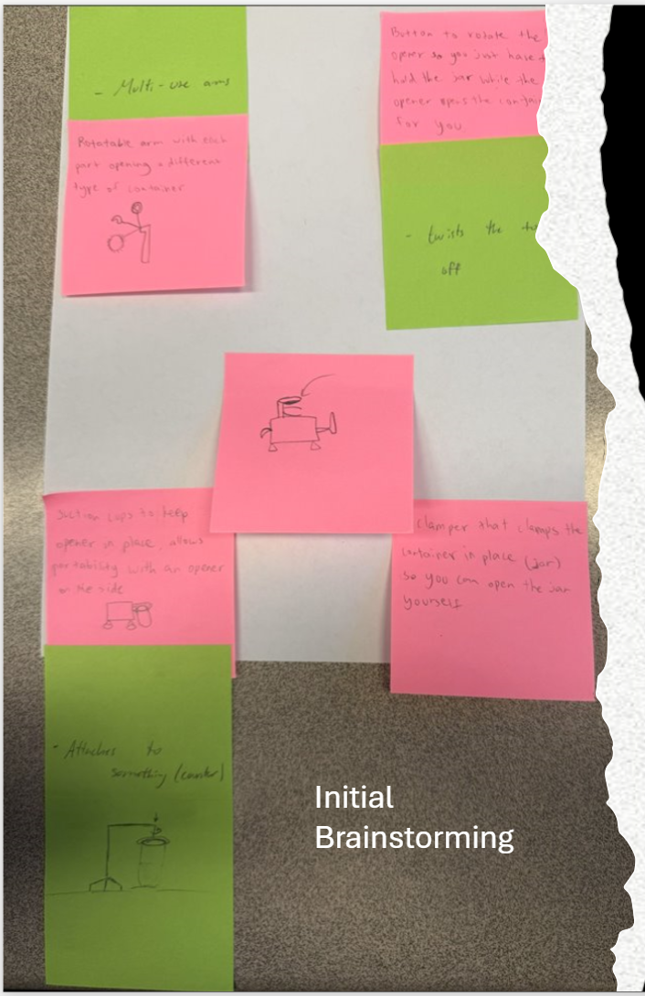
We began with an unconstrained brainstorming session using sticky notes, generating as many ideas as possible before applying any filters. Ideas ranged from motorized mechanisms to purely friction-based passive holders.
Concepts Considered
A powered device that clamps onto a lid and rotates it via a motor. Pros: zero grip strength. Cons: expensive, batteries, bulky, size-specific.
A suction pad anchors the container while a side lever opens it. Pros: good stability. Cons: complex, only works on flat-bottomed containers, fails on textured surfaces.
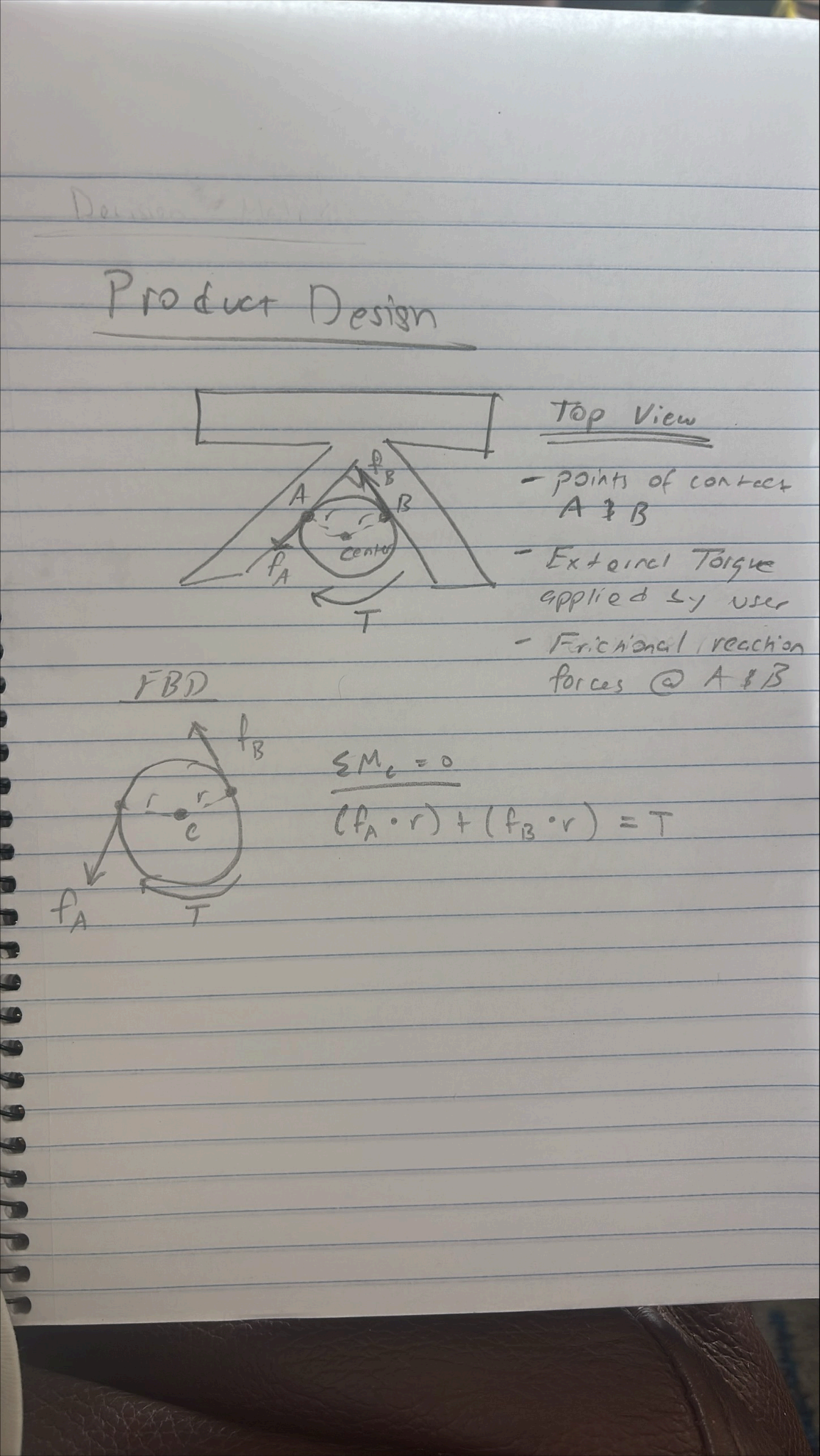
A fixed V-channel that grips the container between two angled walls. The friction replaces the stabilizing hand, freeing the user's single hand to apply torque. Pros: no moving parts, universal sizing, cheap. Cons: relies on counter mounting.
Concept Selection Criteria
- Supports one-handed operation without any setup adjustment per use
- Accommodates multiple container diameters without swapping parts
- Reduces required grip strength via geometry rather than power
- Stable enough to withstand the twisting force applied to a stubborn lid
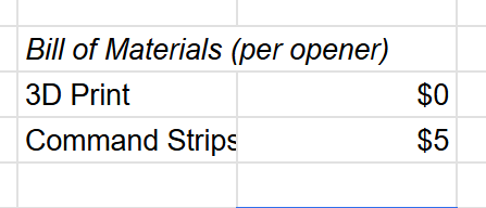
- Simple and inexpensive to manufacture (target: <$5 in materials)
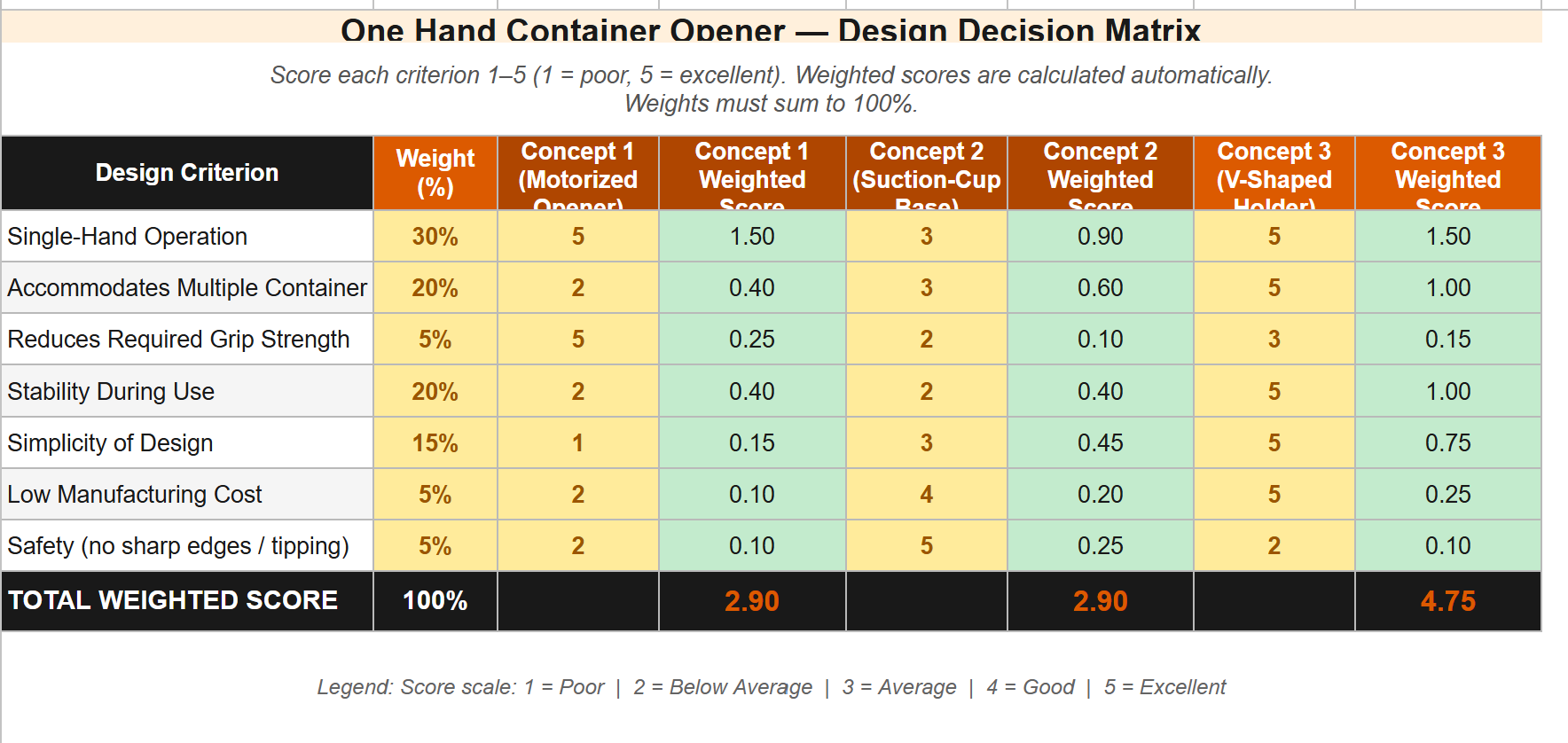
Why We Chose Concept 3
The V-shaped passive holder scored highest on every criterion. The wedge geometry is self-adapting: a wider container simply contacts the walls higher up, while a narrower container seats deeper into the V. The absence of moving parts means nothing can break or jam, and the core geometry can be 3D printed in a single piece.
| Concept | Stability | Force | Accessibility | Total |
|---|---|---|---|---|
| Lever Clamp | 3/5 | 4/5 | 3/5 | 10/15 |
| Countertop Cradle ✓ selected | 5/5 | 4/5 | 5/5 | 14/15 |
| Geared Crank | 4/5 | 5/5 | 3/5 | 12/15 |
Prototyping & Iteration
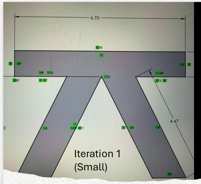
Modeled in CAD with a channel width of approximately 4.47 inches and 3D printed to validate the V-geometry. The principle worked for small containers but the narrow channel could not accommodate larger-diameter containers, revealing size range as our primary design gap.
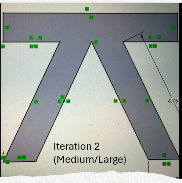
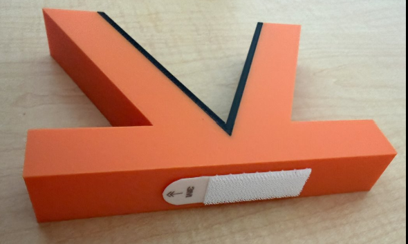
Expanded the channel to approximately 6.75 inches and refined the wall angle to optimize the friction-to-force ratio. This version held a wider range of containers. Testing also showed a bottom friction layer was unnecessary — command strips provided ample mounting force.
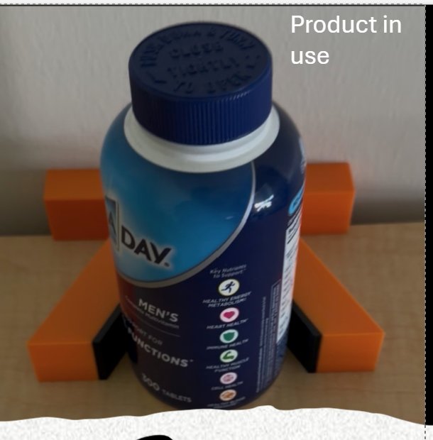
A single-piece 3D-printed V-shaped holder with rubber friction strips lining the inner channel walls, mounted with command strips. The geometry self-centers containers; the rubber lining increases friction; symmetrical design allows both opening and closing; grip height is adjustable by repositioning the command strips.
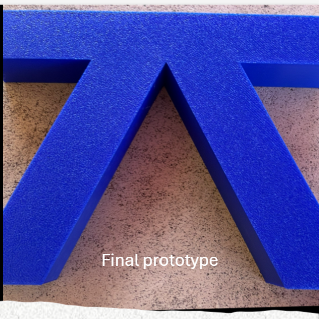
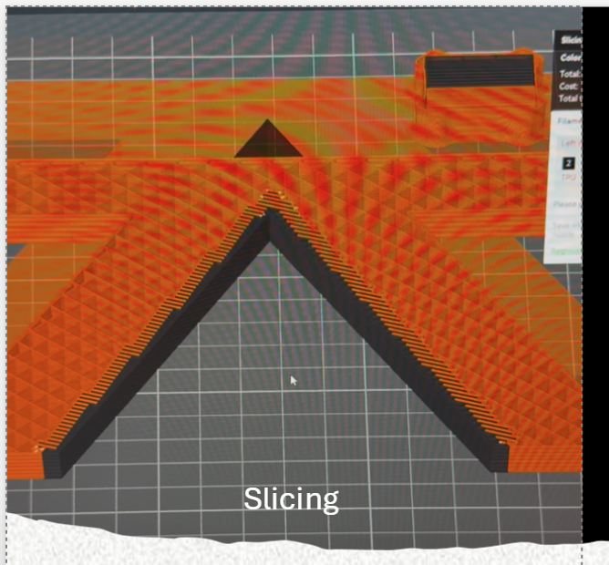
Manufacturing
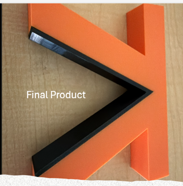
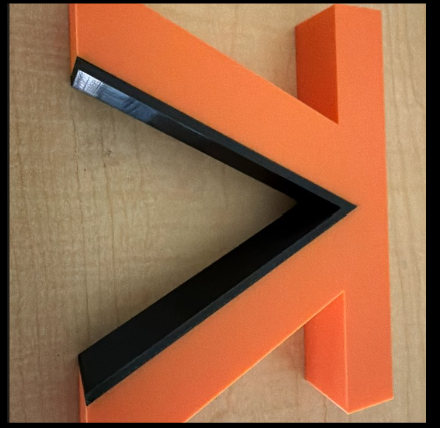
Final Product
Testing & Findings
- Single-hand operation: fully achievable across all tested container sizes
- Setup: one-time; no adjustment between uses
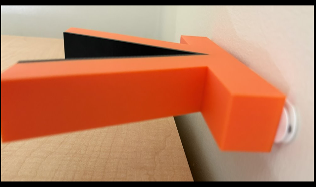
- Stability: command-strip mounting held firmly under twisting force
- Material cost: 3D-printed plastic + rubber strip + command strips kept unit cost minimal
Remaining Tradeoffs
- Requires a flat, stable mounting surface (counter or table)
- Command strips may leave adhesive residue on some surfaces
- Extremely small containers may not seat fully in the V-channel
Individual Reflections
Appendices